Week 5, Assignment 5
3D Scanning and Printing
Video - Week Five, Lecture Five
3D Scanning:
3D Scanning is process which makes the mesh of a real-world object which can be further modified using different modelling tools.
3D Scanner
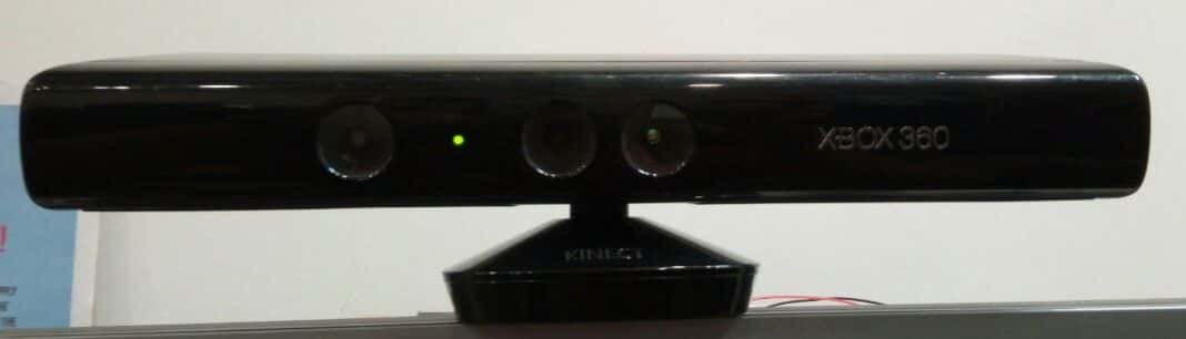
For this week's assignment I used XBox 360 Kinect as a 3D Scanner.
Software Installation
First for using the 3D Scanner I have to install the software for Windows as I was using Windows OS. To get the Software we can Directly Google and download. The Software used for 3D Scanning with XBox 360 Kinect was Skanect, here I downloaded the free version of its which was for "Non-Commercial use only", this version was having some limitation as the compared to paid version like, no colors are shown after scanning, etc. but it worked and served the purpose for which I was using.
About XBox 360 Kinect
Before beginning I preferred to know more about the Scanner and its specifications, and I wanted to have some more information about 3D scanning how it scans and all things needed while scanning.
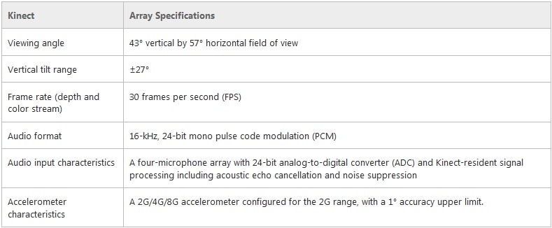
So, in Kinect there are couple of sensors on the scanner, which detects the object and tell us about it. Basically 3D Scanner collect information about objects within a set visual field, but unlike cameras, 3D scanners collect an information about an object’s position in space instead of its color and appearance. This is possible by calculating the distances between the scanner and various points of an object’s surface. A laser is shone onto the object of interest which then reflects the laser back to the scanner. The scanner is also equipped with a sensor that collects data from the laser about the object’s shape.
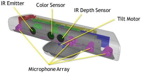
• An RGB camera that stores data in a 1280x960 resolution. This makes capturing a color image possible.
• An infrared (IR) emitter and an IR depth sensor. The emitter emits infrared light beams and the depth sensor reads the IR beams reflected back to the sensor. The reflected beams are converted into depth information measuring the distance between an object and the sensor. This makes capturing a depth image possible.
• A multi-array microphone, which contains four microphones for capturing sound. Because there are four microphones, it is possible to record audio as well as find the location of the sound source and the direction of the audio wave.
For more Depth Information visit the reference link below:
Scanning:
As now after knowing about scanner and after installing the software it's now time for action. So I started with opening the software, the user interface is so very simple of Skanect that even someone if using it for the first time doesn't need any kind of learning or tutorial to follow its usage. To start with after opening the software I started a New File were as I was going to scan Me I choose "Body" in Scene and Started scanning.

After starting the Scanning in the next Record window I simply clicked the record button and the scanning started soon after 3 second of countdown.
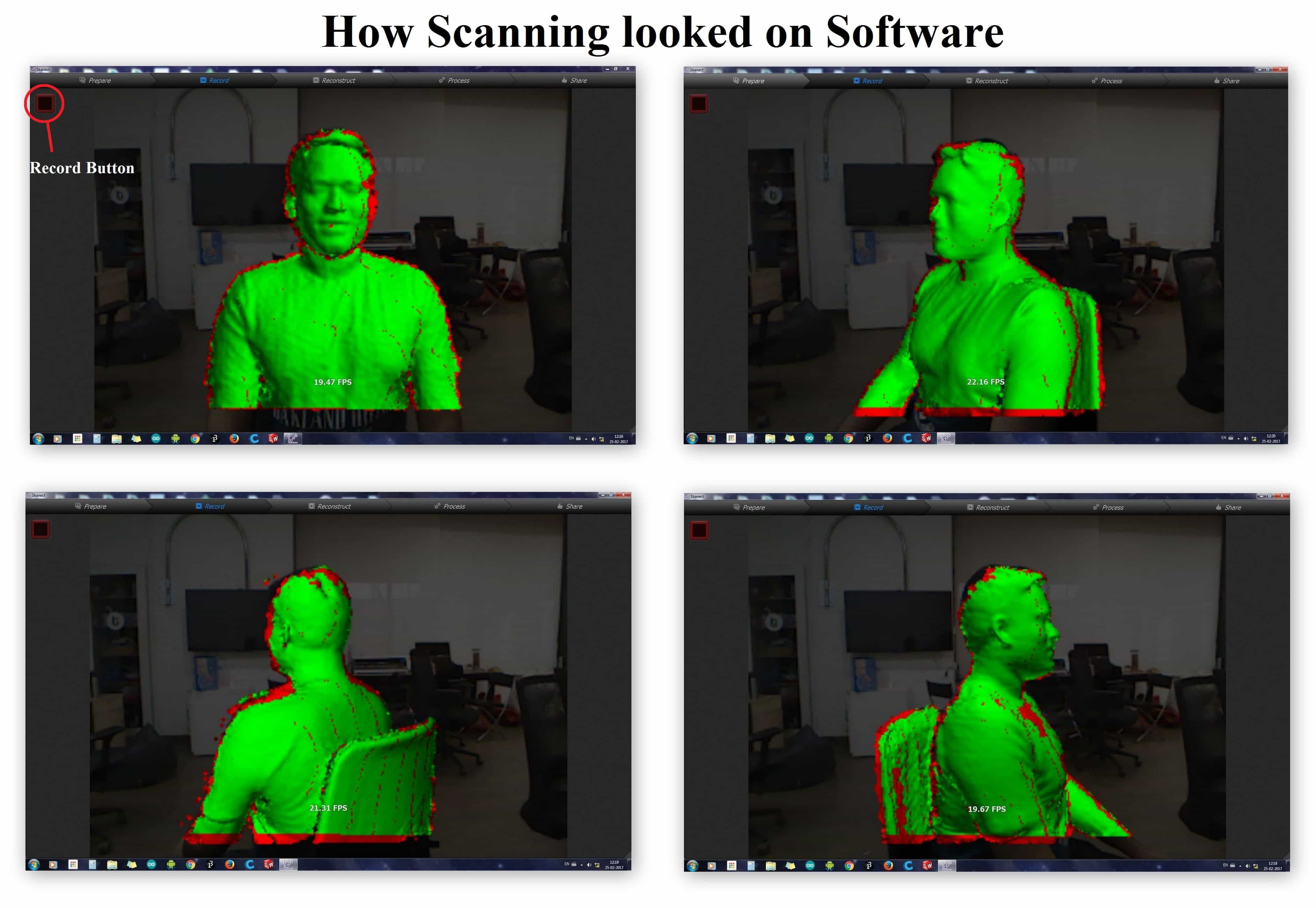
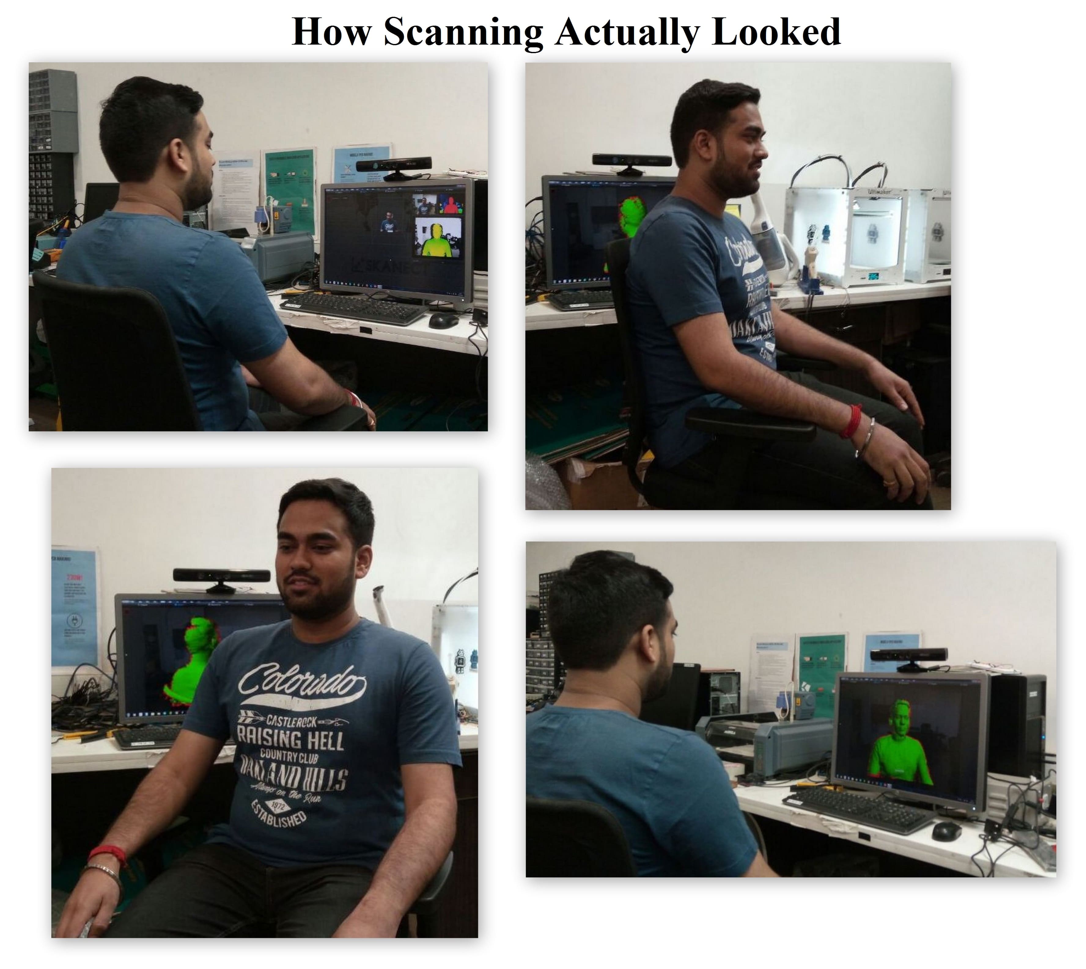
After the scan was complete and stopping the Record option, the software takes some time to construct and show the Scanned object. As it shows I was also able see the whole path traced by me while rotating, and as smooth as the path look the body scanned on software comes more precisely.

Then after finishing the Record part, I switched to Reconstruct window next to it where I just run the Fidelity to Low and reconstructed. Then after the reconstruct was done in the next window of Process in Geometry column there was Fill Holes option which will fill all the hollow parts on the scanned file and make it much more better then the before. So here I just Run the fill holes option at a Very Low Smoothing process as it was taking very much time while running it with Low Smoothing. After fill holes then it was time to remove the unwanted parts from the file scanned so just below Fill Holes was Move & Crop option which moved the File in such a manner that whatever was below the Blue Bottom surface was removed. After adjusting the file accordingly I wanted to Remove some parts from the file was not needed, so In Remove Parts Option just Run the command and see the magic.
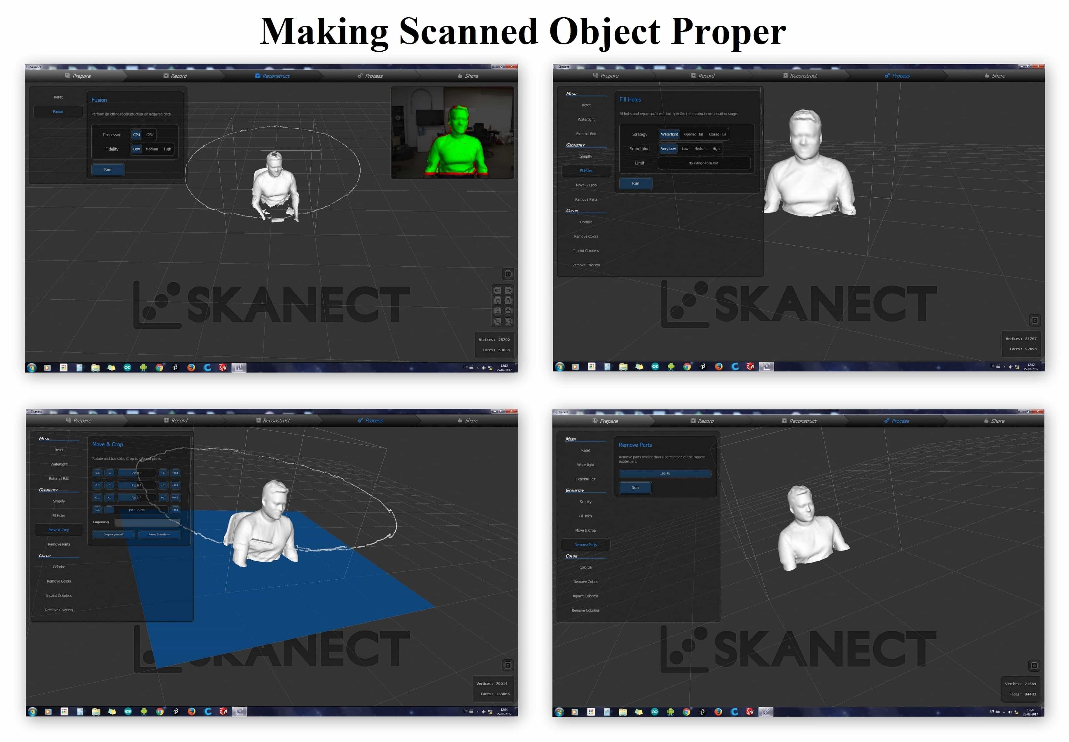
Finally now it was time to save the file. So after performing all operation in the Process Windows and made the file good, now went to the next window of 'Share' were I was able to Save my Scanned object in various file formats such as, .ply, .stl, .obj, etc.
3D Scanned File can be downloaded from here:
Jatin 3D Scanned file in '.STL' format
Jatin 3D Scanned file in '.PLY' format
3D Printing:
3D Printing also known as additive manufacturing (AM), is one of the most influencing technology now a days. 3D printer are now so popular that with only a basic knowledge anyone can build his/her own printer with ease.
3D Printing, also known as Rapid Prototyping machine, refers to various processes used to synthesize a three-dimensional object. In 3D printing, successive layers of material are formed under computer control to create an object. These objects can be of almost any shape or geometry and are produced from a 3D model or other electronic data source. A 3D printer is a type of industrial robot. ~ Wikipedia
Need of 3D Printing over Subtractive Manufacturing:-
Subtractive manufacturing is a process by which 3D objects are constructed by successively cutting material away from a solid block of material. Subtractive manufacturing can be done by manually cutting the material but is most typically done with a CNC Machine. So compared to 3D printing subtractive manufacturing is not used for prototyping phase as it takes a lot of time, so, additive manufacturing is preferred over subtractive manufacturing.
The Process of 3D printing is chosen over Molding as it takes less time and less efforts to know the product better, instead of making mold, here we can directly print an object from a 3D designing software. But when it comes to mass production 3D printing is not the solution, it is only good for testing the product as a prototype.
Working of 3D Printer:
3D Printing is one of the rapid prototyping process which involves the plastic like substance like PLA, ABS, HIPS, etc. majorly as FDM technology deals with only Polymers as printing material. So starting from making a virtual design of the object in the form of CAD file it is made to a 3D Object. As the 3D model is ready it has to be saved in ‘.STL’ format as this format makes our 3D model into binary form which is read by the 3D printing software.
The 3D Model is then feed to the software and all the required settings are madeand then the file is converted to ‘.gcodes’ and the g-code file then saved to the SD Card which is inserted into the printer as the printer only reads g-codes for printing. Now the object is ready to be 3D printed Layer by Layer.
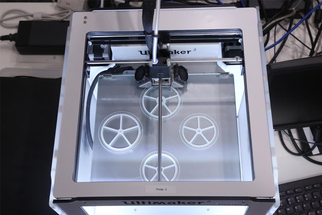
3D printer which I have in Lab is a FDM machine (Fused Deposition Modeling) which works using a plastic filament which is unwound from a coil and supplying material to an extrusion nozzle which can turn the flow on and off. The nozzle is heated to melt the material and can be moved through the Pipe into the nozzle by a numerically controlled mechanism. The object is produced by extruding melted material to form layers as the material hardens immediately after extrusion from the nozzle. This technology is most widely used with two plastic filament material types: ABS (Acrylonitrile Butadiene Styrene) and PLA (Polylactic acid). Though many other materials are available ranging in properties from wood fill to flexible and even conductive materials.
Group Assignment:
Testing the 3D Printing Limit:-
To test the 3D printing limit I printed out a standard test print, which have various cases which test the limit of the printer. I downloaded this test print from ‘Thingiverse’ which can be found here 3D Printer Test Print
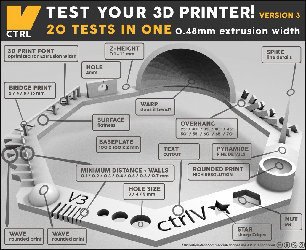
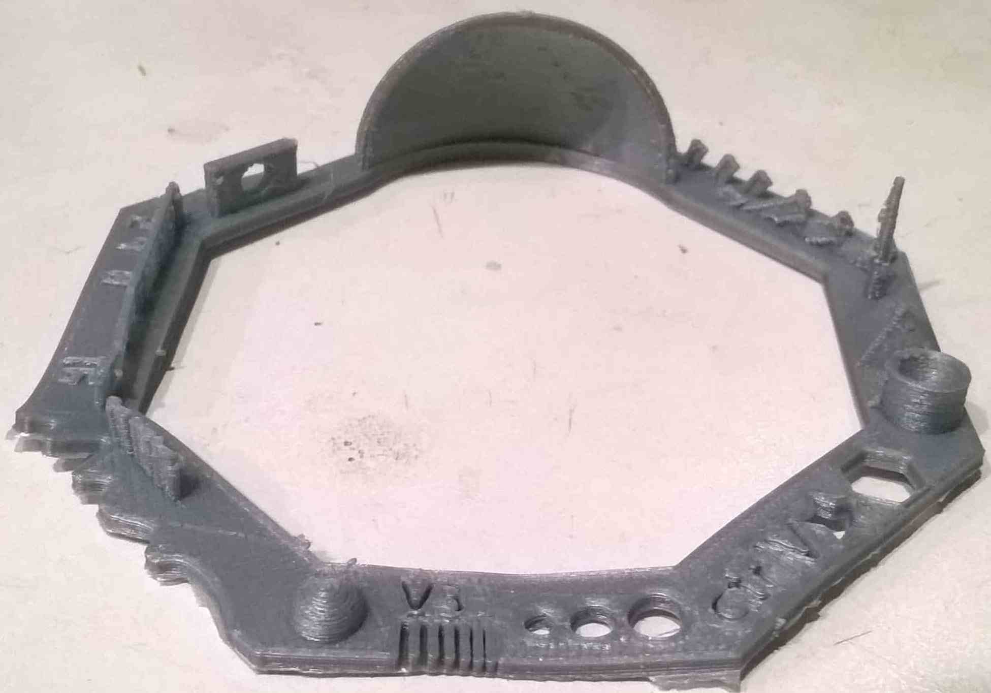
The shapes included in the design are
02 Wave, rounded print - Looks Good
03 Star, Sharp Edges - Looks Fine
04 Name, Complex Shapes - Nicely Printed
05 Holes, Size 3, 4, 5 mm - Matches Exactly with Size
06 minimal Distance: 0.1, 0.2, 0.3, 0.4, 0.5, 0.6, 0.7 mm - 0.1 & 0.2 mm gap wasn't that clear, maybe because it was printed as Raft
07 Z height: 0.1, 0.2, 0.3, 0.4, 0.5, 0.6, 0.7, 0.8, 0.9, 1.0, 1.1 mm - Fine
08 Wall Thickness: 0.1, 0.2, 0.3, 0.4, 0.5, 0.6, 0.7 mm - Printed Fine
09 Bridge Print: 2, 4, 8, 16 mm - Good
10 Sphere, Rounded Print 4.8mm height - Good
11 Sphere Mix, 7 mm height - Nicely Printed
12 Pyramide, 7 mm height - only the top point was not good
13 Overhang: 25, 30, 35, 40, 45, 50, 55, 60, 65, 70° - Printed all but after some time broke
14 Warp, does it bend? - No it doesn't
15 3D Print Font, optimized for 3D printing - Good
16 Surface, Flatness - Good
17 Size, 100 x 100mm x 23.83 (10mm width) - Fine
18 Spike, minimum Layer Time, 21 mm height from Bottom (include Baseplate) - printed in just 1 hrs 16 min, was good enough
19 Hole in Wall, 4 mm diameter, check for proper print - Matched Dimensions
20 Raft Test, raft should be just under the model - Filled some gaps wasn't that good
21 Retract Travel, check retract settings for longer travel - Fine
Individual Assignment:
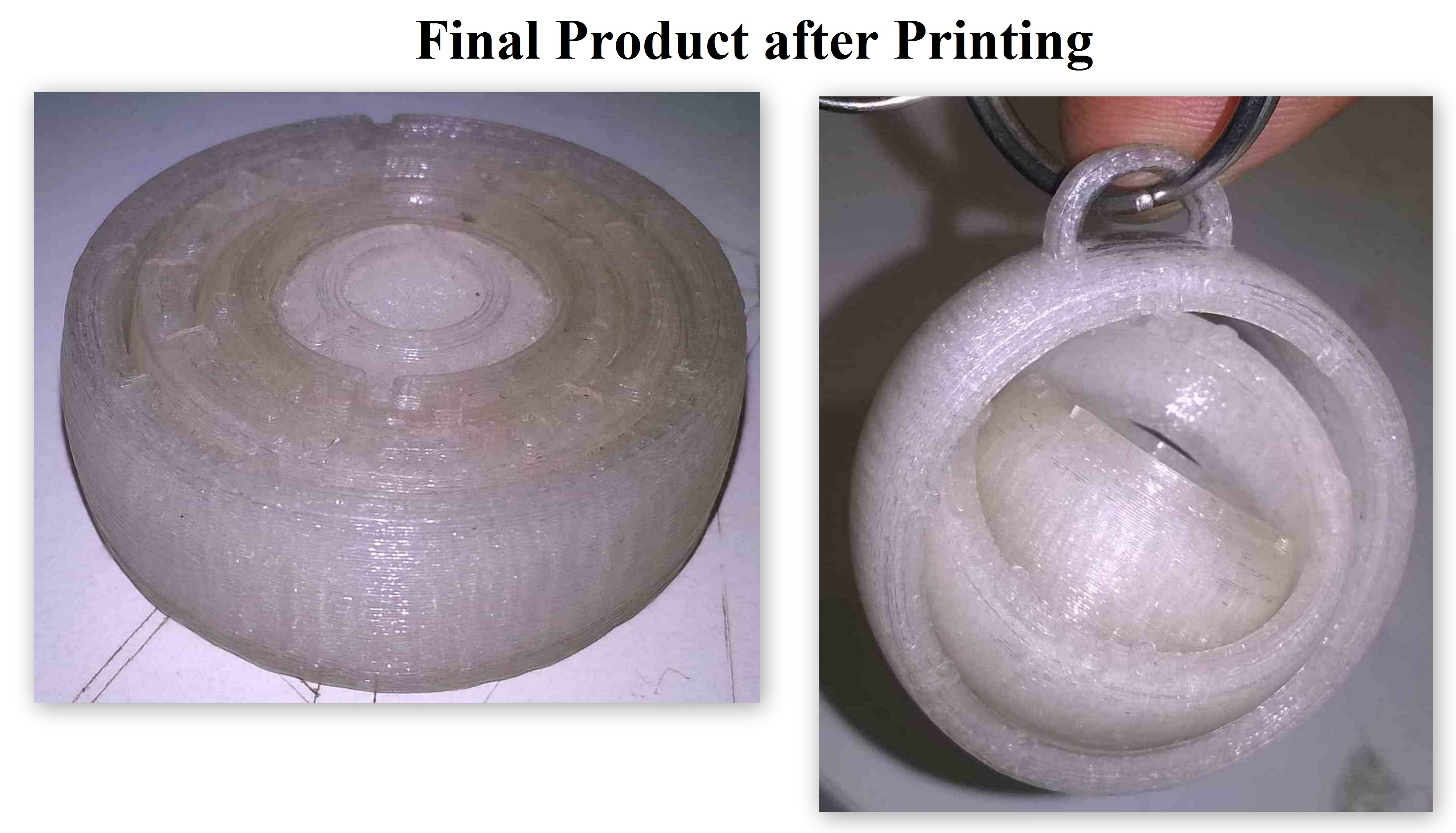
In this individual assignment I designed and printed a Gyroscope.
Design:-
While designing the Gyroscope, I just made 4 rings in Gyroscope of different diameters so that it can fit inside each other and so that it should not come out of each other I made the Rings a bit curvy, you can see it below in the screenshot of the design.
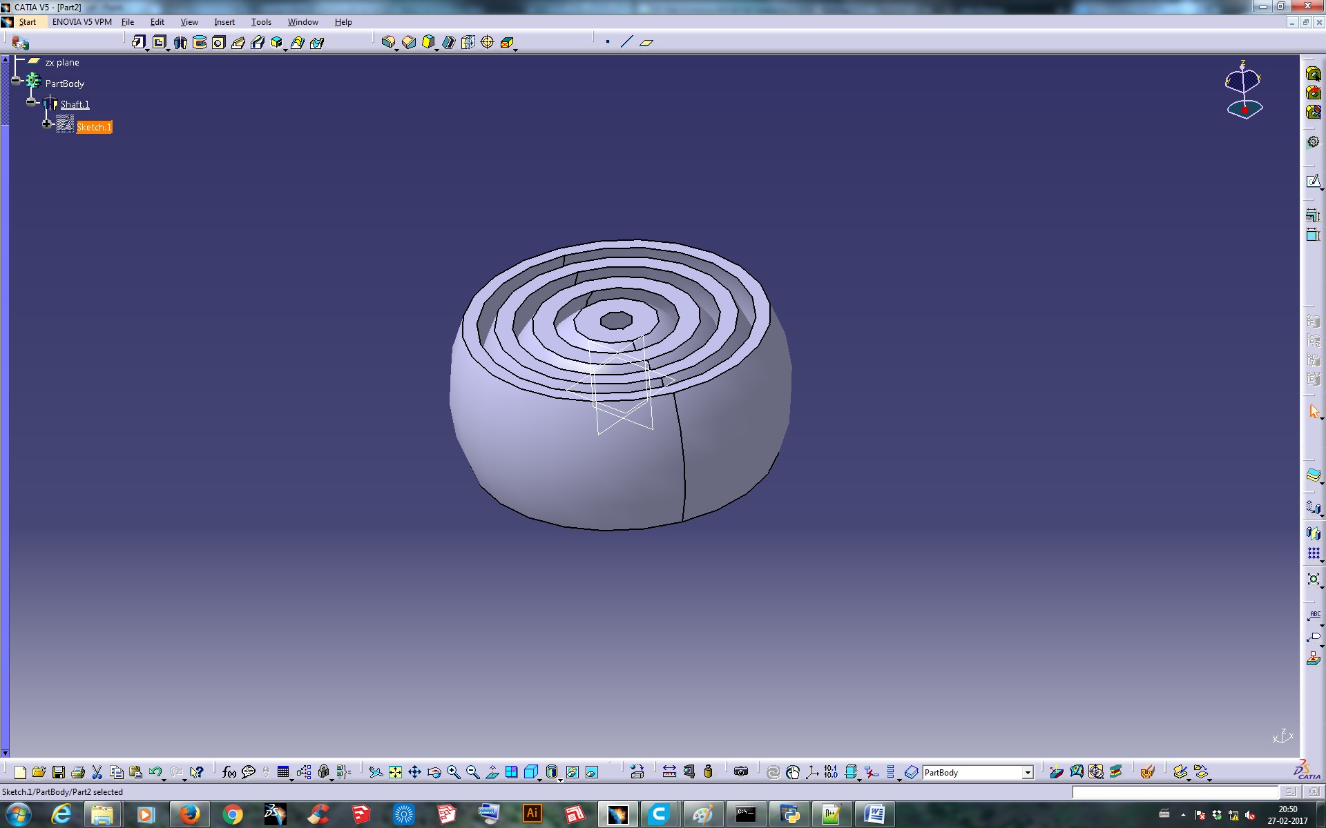
Why it can't be made Subtractively
It was not possible to make it subtractively because its having 4 Rings interlocked one inside another which is not possible for any machine to make it just by subtracting the material. Even subtractively it can't be made moveable or rotatary one inside the other, thats the main reason that I am making it in additive manufacturing process.
Printing Process:
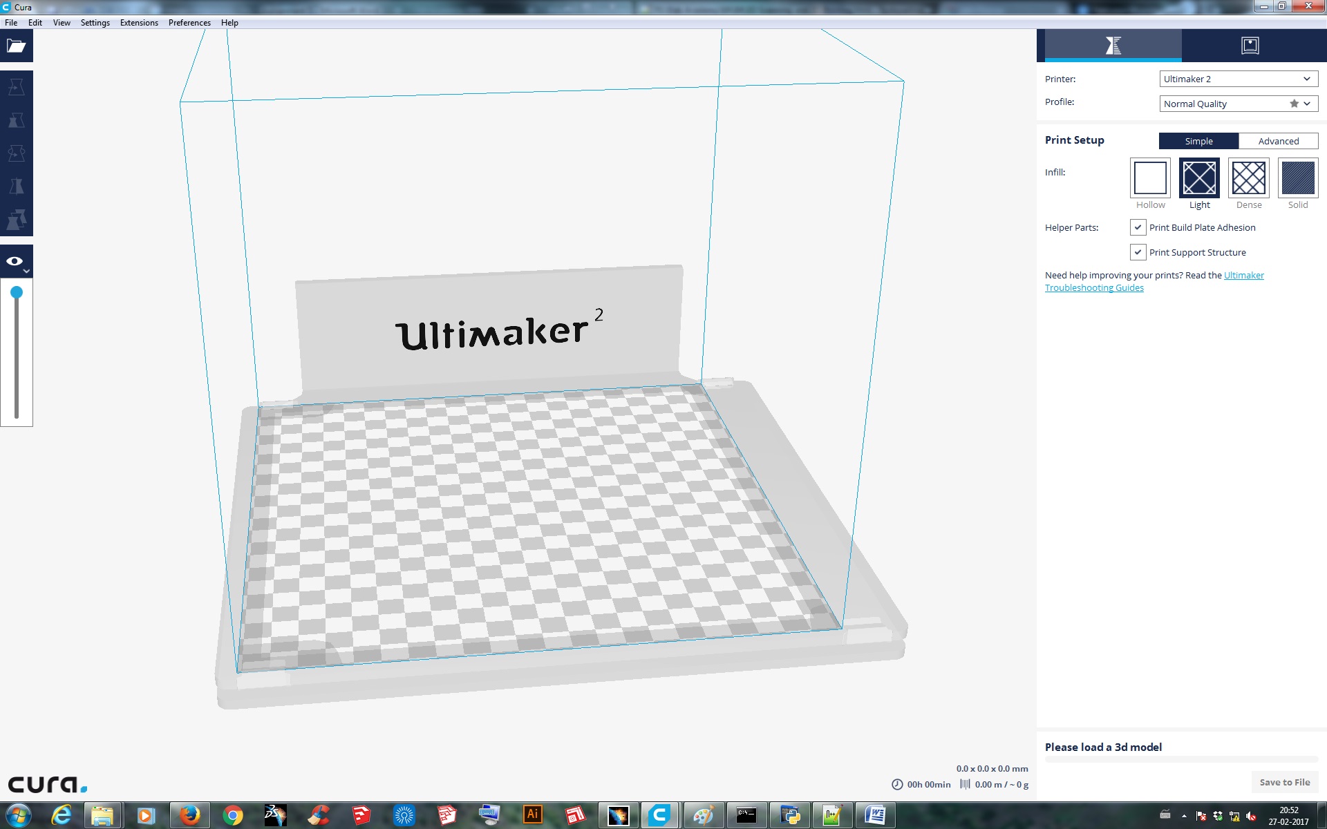
I imported the file in the machine software for Ultimaker 2, which is CURA. There are tools available to set the object properly on the printing bed. Proper alignment of the object is necessary if not done properly the object may not be printed properly or may be extra support material will be printed. So to avoid these errors the software provides a tab to Lay Flat the object on the print bed.
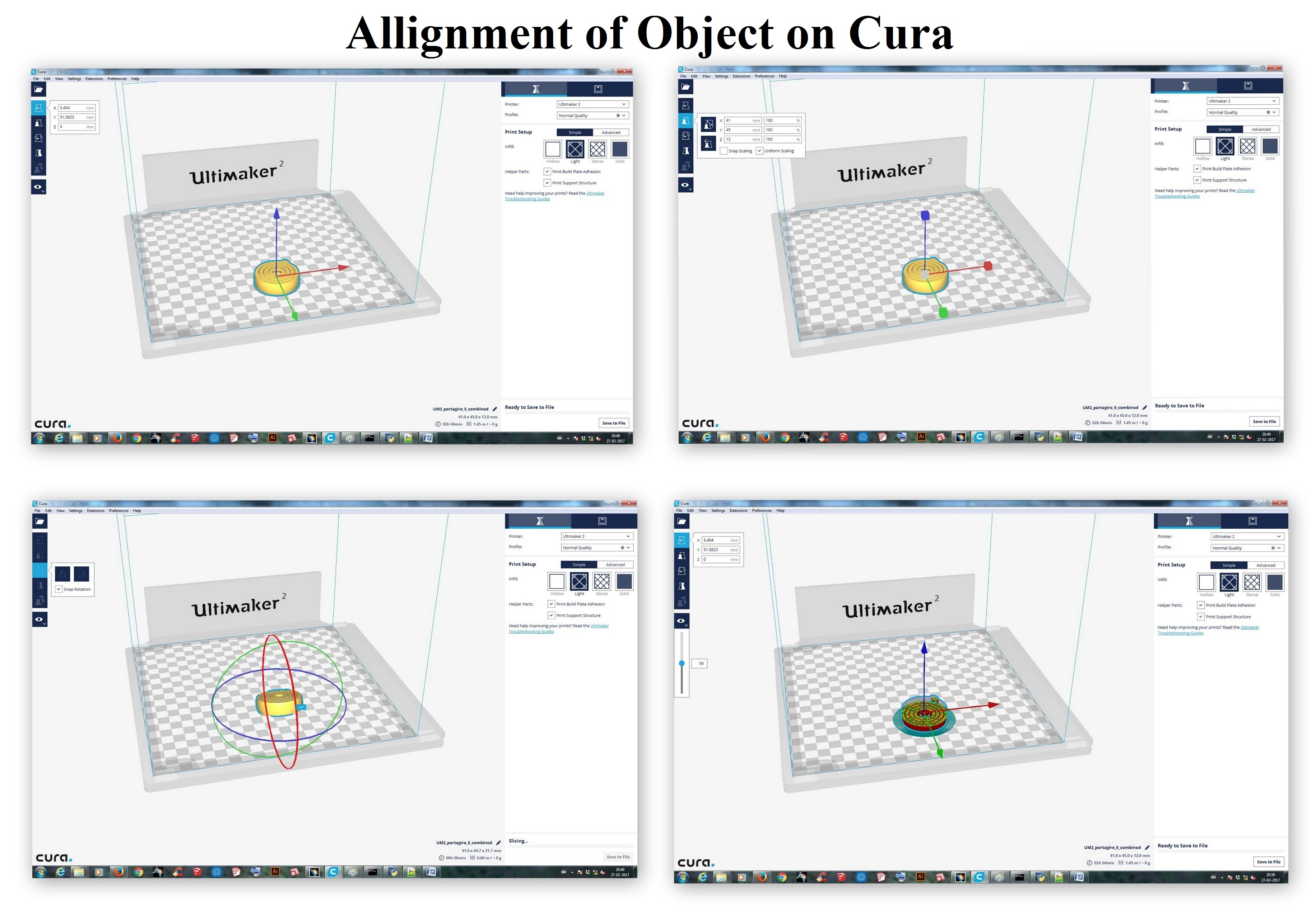
After aligning the object properly now I set the parameter to print the object, which is as follows:
Quality
Layer height : 0.1 mm
Shell thickness :0.8mm
Fill
Bottom/top thickness : 0.8mm
Fill density : 20%
Speed
Print speed : 60 mm/s
Later just saved the file as g-codes and copied it to the SD Card and the object is ready to get printed, but before that just check the bed alignment with the nozzle, it is supposed to of a Paper Thin distance between them. After bed aligning now the printer is ready to print the desired object, so now just start the print.
Final Product after printing:
Download the .stl files from here: